| F2 series management media converter supports WEB management, SNMP sofware management and Console management. Customers conveniently view and set all the local modules and the remote standalone via management interface, including the function of enable/disable a certain port, setting the port rate, duplex mode, twist-pair port speed limitation and resetting the chassis, single module or remote end standalone device. |
| Specifications |
|---|
| Hardware Function |
|
• Support 10Base-T, 100Base-TX, 100Base-FX • Fully compatible with IEEE802.3, IEEE802.3u, IEEE802.3x standards • Up to 5km distance on multi mode optical port and 120km distance on single mode optical port • High-performance auto-negociation chips make sure the data transfer with higher security, stability and without block • Up to 1916 bytes package forwarded • Support half/full duplex mode Auto-negociate • Low power consumption, low heat generation and excelent compatibility • 10Watt professional comunication power supply module inside the standalone. chassis supports double redundant power supply modules and each power supply module supports up to 100 Watt power output for the security and stability • Support hot-swap for all the modules, but not including management module • Single-strand/dual-strand optical module selectable, FC/SC/ST optical port selectable and standalone/16-slot chassis selectable |
| Software Function |
|
• Support local and remote management • Support Console, WEB and SNMP management • Show details of system information, including chassis name, location information, IP address, start-up time, software and hardware version • View & configure the working function of local and remote device, including connection status, speed, half/full duplex mode, port status • Set the speed limitation from 0Mbps to 70Mbps by step of 32Kbps • Support remote loop back function, three loop back position selectable. Help to find out the line fault conveniently • Summarize the data flow information and show the communication state of each port • Support SNMP management. Set Trap Destination and Community Name, including the authority • Reset the system or a single module or the remote end device via management software • Reset chassis to factory default • Show the detailed information of power supply, including AC/DC type and running status • Provide MIB file, make it easy to be integrated into the third party SNMP management software • Adopt centralized management style and the three-view catalogue, which can manage many sets of chassis at the same time in one single window. Meantime, it's very easy and clear to manage all devices even if many chassis in one window. |
| Interface Specification | ||||||||||||||||||||||||||||||||||||||||||
|---|---|---|---|---|---|---|---|---|---|---|---|---|---|---|---|---|---|---|---|---|---|---|---|---|---|---|---|---|---|---|---|---|---|---|---|---|---|---|---|---|---|---|
| Fiber Interface Specification | ||||||||||||||||||||||||||||||||||||||||||
|
1) Adopt standard 1*9 pin optical transciever module; 2) Wavelength: 850nm, 1310nm on multi-mode; 1310nm, 1550nm on single-mode; 3) Up to 120km transmission distance on single-mode; 4) SC/ST/FC optical connectors are selectable. Optical Power Budget List: |
||||||||||||||||||||||||||||||||||||||||||
|
||||||||||||||||||||||||||||||||||||||||||
| Ethernet Port | ||||||||||||||||||||||||||||||||||||||||||
|
Fully compatible with IEEE802.3, IEEE802.3u and IEEE802.3x Standards; 1) Data Rate: 10/100Mbps auto-negotiation; 2) Half/full duplex mode auto-negotiation; 3) Connectors: RJ45 Jack; 4) Support automatic MDI/MDI-X crossover. |
| General Specifications | |
|---|---|
| Device size | |
|
Standalone: 132mm (width)x36mm (depth)x122mm (height) 19-inch Chassis: 440mm (width)x125mm (depth)x250mm (height) |
|
Power |
|
|
AC: 220VAC±20%, 50/60Hz DC: -40 ~ -57 VDC Power consumption: Standalone < 3W, Chassis full of modules <50 W |
|
Environment |
|
|
Working environment: Temperature: 5°C ~ 40°C; Humidity: 30% ~ 90% (25°C); Atmosphere pressure: 86 kPa ~ 106 kPa. Store and transportation environment: Temperature: -20°C ~ 60°C; Humidity: 20% ~ 90% (25°C); Atmosphere pressure: 86 kPa ~ 106 kPa. |
|
| Appearance | |||||||||||||||||||||||||
|---|---|---|---|---|---|---|---|---|---|---|---|---|---|---|---|---|---|---|---|---|---|---|---|---|---|
| Standalone Appearance | |||||||||||||||||||||||||
|
|||||||||||||||||||||||||
Table 1 LED Description |
|||||||||||||||||||||||||
|
|||||||||||||||||||||||||
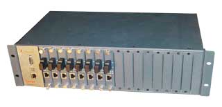
Chassis Appearance |
|||||||||||||||||||||||||
|
|||||||||||||||||||||||||
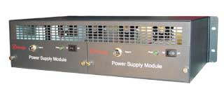
Chassis Inside |
|||||||||||||||||||||||||
|
|||||||||||||||||||||||||
| Typical Applications | |
|---|---|
|
|
| Management Port Set | |
|---|---|
| RS-232 Management Port | |
|
Baud Rate: 57600 Data Width: 8 Odd/Even Parity: None Stop Bit: 1 Flow Control: None Connector: DB9, Male |
|
Twist-pair Management Port |
|
|
Port Speed: 10/100Mbps auto-negotiation Auto-negotiate on half/full duplex mode Connector: RJ45 |
|
Default User and Password |
|
|
Name: admin Password: No Password |
|
Default IP Address |
|
| The default IP address of the chassis: 192.168.0.216 | |
| Installation | |
|---|---|
| Standalone Installation | |
|
1) Connect the fiber strand and twist-pair cable according to the practical application environment, then connect the power; 2) Connect the power supply, the media converter will do the self-test. During the test, all LEDs will blink one by one; 3) After reset, if the line connects correctly, the LEDs PWR, Tlink and Flink will light on. That means the twist-pair port and fiber port connect normally. The 100M LED is on while link speed is 100Mbps at twist-pair port; 4) If OK, then the line is connected; 5) When transferring data,Tlink and Flink will blink. |
|
Chassis Installation |
|
|
1) Insert the modules into the chassis one by one; 2) Fix the chassis to a certain place; 3) Connect the two power supply modules to power source with power cable; 4) Switch on the power supply, each media converter module will be self-tested and all LEDs will blink one by one; 5) If OK, then the line is connected; 6) When transferring data, Tlink and Flink will blink. |
|
| FAQ: Failures & Solutions | |
|---|---|
|
1. Failure: Power LED is off. Solution: Check-up the device if the power cable is connected correctly. 2. Failure: Tlink is off after reset with twist-pair port connected Solution: (1) Check if the twist-pair cable is connected correctly. (2) Check if the Ethernet device connected with the converter is running normally. 3. Failure: Flink is off after reset with optical port connected Solution: (1)Check if the fiber is connected correctly. (2)Failure connection of transmit or receive side may lead to the Flink led off .So need to check if the TX or RX connection of the fiber port is normal. 4. Failure: Data transfer abnormally, including transferring failure, data loss Solution: (1) Check if the transmit power of converter optical port is normal; (2) Be sure no single-mode fiber connected with multi-mode equipment; (3) Check if it is used in pairs when single-strand converter is used. 4. Failure: The device doesn't work after normal state for a while. That is to say, the media converter doesn't transfer data, but if reset, it will work normally. Solution: It is usually caused by the Ethernet switch. In normal status, the switch will take CRC and package length check, and drop the bad package. However, some bad ones could not be inspected and thus could not be sent out or dropped, so these bad packages will be stored in the buffer one by one, until the switch is filled up, which brings about the failure of the switch. Try to connect the converter with PC directly to see if the failure is not existed. |
|